Printed Circuit Boards form the backbone of modern electronic devices, facilitating the seamless transmission of signals across various components. Within these intricate designs, transmission lines play a crucial role in maintaining signal integrity and reducing electromagnetic interference. Among the most commonly used transmission lines in PCBs are microstrips and striplines. Each type offers distinct advantages and challenges, making the choice between them significant for the performance and reliability of the final product.
This article aims to provide a clear and concise comparison of striplines and microstrips, highlighting their structural differences, performance characteristics, and typical applications. By understanding these aspects, PCB designers and engineers can make informed decisions tailored to their specific project requirements, ensuring optimal signal transmission and overall device performance.
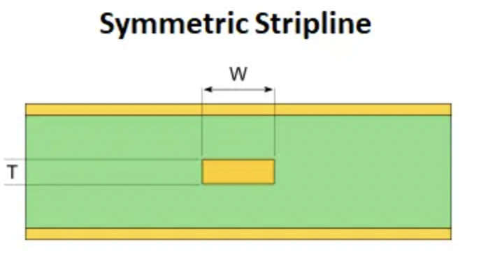
A stripline is another type of transmission line used in PCB designs, characterized by a conductor strip sandwiched between two parallel ground planes, with the entire assembly embedded within the dielectric material of the PCB. This internal placement provides excellent shielding for the signal path, reducing electromagnetic interference (EMI) and crosstalk from adjacent traces. Striplines are predominantly used in multi-layer PCB designs, offering robust performance for high-frequency and high-speed applications.
Striplines are ideal for applications that demand high signal integrity and minimal interference. They are commonly used in high-frequency circuits, aerospace and military electronics, and any design where maintaining the purity of the signal is critical. The inherent shielding provided by the ground planes makes striplines suitable for environments with stringent EMI requirements.
Striplines offer several notable performance advantages:
Signal Integrity: The central placement of the stripline between two ground planes provides superior shielding, which significantly reduces radiation losses and crosstalk. This configuration ensures high signal integrity, especially important for high-speed digital and RF signals.
Dielectric Losses: While striplines generally experience higher dielectric losses compared to microstrips, the consistent dielectric environment around the stripline helps maintain a stable propagation constant.
Impedance Control: The characteristic impedance of a stripline is influenced by the width of the conductor strip and the spacing between the ground planes. This allows precise control over impedance, making striplines suitable for impedance-controlled routing in high-density PCB designs.
Designing with striplines involves several key considerations:
Complexity: The internal routing of striplines makes the design and manufacturing process more complex compared to microstrips. However, this complexity is offset by the benefits in signal integrity and EMI control.
Cost: Striplines can be more expensive to implement due to the need for precise manufacturing and the additional layers required for the ground planes.
Debugging and Prototyping: The embedded nature of striplines can complicate debugging and prototyping, as accessing the internal layers for testing or modifications is more challenging compared to surface traces like microstrips.
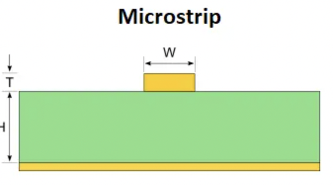
A microstrip is a type of transmission line used in PCB designs, consisting of a conducting strip separated from a ground plane by a dielectric layer. Typically, the conducting strip is placed on the external layers of the PCB, with the dielectric material (such as FR4) acting as an insulating layer between the strip and the ground plane. This open structure allows the microstrip to interface easily with other components, making it a popular choice for RF and microwave circuits.
Microstrips are widely used in applications that require high-frequency signal transmission, such as RF circuits, microwave communication systems, and antenna designs. Their ease of connectivity and minimal crosstalk in high-density environments make them ideal for integrating multiple channels on a single PCB. Additionally, microstrips are commonly employed in designs where rapid signal propagation and efficient heat dissipation are crucial.
Microstrips offer several performance benefits:
Propagation Speed: Microstrips have a lower propagation constant, resulting in faster signal transmission compared to other types of transmission lines.
Dielectric and Radiation Losses: While microstrips experience lower dielectric losses due to their partial exposure to air, they tend to have higher radiation losses, which can affect signal integrity, especially at higher frequencies.
Impedance Control: The characteristic impedance of a microstrip can be easily controlled by adjusting the width of the strip and the thickness of the dielectric layer, providing flexibility in design.
Designing with microstrips involves several considerations to ensure optimal performance:
Manufacturing Ease: Microstrips are relatively easy to manufacture, as their placement on the PCB surface simplifies the process of connecting components and reduces production costs.
Thermal Management: The open structure of microstrips allows for effective heat dissipation, making them suitable for applications where thermal management is a concern.
Signal Integrity: To minimize radiation losses and crosstalk, designers must carefully plan the layout and spacing of microstrip lines, particularly in high-density and high-frequency applications.
Understanding the key differences between striplines and microstrips is essential for making informed decisions in PCB design. These differences significantly impact performance, application suitability, and design complexity.
Microstrips are located on the external layers of the PCB, where a conducting strip is separated from a ground plane by a dielectric layer. This open structure means the microstrip is exposed to air above the PCB and the dielectric material below. In contrast, striplines are embedded within the internal layers of the PCB, sandwiched between two parallel ground planes. This placement provides a consistent dielectric environment around the signal trace, enhancing shielding and reducing electromagnetic interference (EMI).
In terms of signal integrity and shielding, microstrips tend to exhibit higher radiation losses due to their exposure to air, making them more susceptible to external interference. However, they offer good performance for high-frequency signals where ease of connectivity is prioritized. Striplines, on the other hand, benefit from their embedded nature, which provides excellent shielding from external EMI. This results in lower radiation losses and improved signal integrity, making striplines ideal for high-speed and high-frequency applications where maintaining signal purity is crucial.
Regarding dielectric and radiation losses, microstrips experience lower dielectric losses because part of the signal propagates through the air, which has a lower dielectric constant compared to the PCB material. However, the trade-off is higher radiation losses. Striplines encounter higher dielectric losses due to the consistent dielectric environment provided by the surrounding PCB material. Nonetheless, this environment helps minimize radiation losses, maintaining a more stable signal path.
Impedance control in microstrips is relatively straightforward by adjusting the width of the conducting strip and the thickness of the dielectric layer. This flexibility makes microstrips suitable for a wide range of applications with varying impedance requirements. For striplines, impedance control is achieved by manipulating the width of the conductor and the spacing between the ground planes. This precise control is advantageous for designs requiring stringent impedance tolerances, especially in high-density routing scenarios.
When it comes to manufacturing complexity and cost, microstrips are generally easier and less expensive to manufacture due to their external placement. The simpler design process makes microstrips a cost-effective solution for many RF and microwave applications. Striplines, however, are more complex and costly to produce because of the additional layers and precision required for embedding the signal traces. This complexity is justified in applications where the benefits of reduced EMI and superior signal integrity outweigh the higher production costs.
Understanding the different routing styles for striplines and microstrips is crucial for optimizing PCB designs. Here are some common routing styles for both types:
Standard Microstrip: A single conducting strip placed on the external layer of the PCB, separated from the ground plane by a dielectric layer. This is the most basic and common microstrip configuration.
Edge-Coupled Microstrip: Two parallel microstrip lines routed close to each other, often used for differential signaling. This configuration helps to minimize crosstalk and maintain signal integrity in high-speed applications.
Embedded Microstrip: Similar to standard microstrip but embedded within the PCB layers, with a dielectric material above and below the strip. This configuration is less common and used in specific applications requiring additional shielding.
Symmetric Stripline: A conducting strip centrally placed between two parallel ground planes within the internal layers of the PCB. This symmetrical structure provides consistent dielectric surroundings and excellent EMI shielding.
Asymmetric Stripline: Similar to symmetric stripline but with the conducting strip placed closer to one of the ground planes rather than centrally. This configuration can be used to achieve different impedance characteristics.
Edge-Coupled Stripline: Two parallel striplines routed close to each other, used for differential signaling within the internal layers of the PCB. This configuration provides excellent shielding and minimal crosstalk.
Broadside-Coupled Stripline: A pair of striplines stacked one above the other within the PCB layers, with the dielectric material separating them. This configuration is used for differential signaling and provides excellent isolation and signal integrity.
Choosing between stripline and microstrip transmission lines is essential for optimizing PCB performance. Microstrips are cost-effective and easier to manufacture, ideal for RF and microwave circuits. Striplines offer superior signal integrity and EMI shielding, making them suitable for high-speed and high-frequency applications.
Evaluate your project’s specific needs, such as frequency, signal integrity, and cost considerations. Consulting with a knowledgeable PCB manufacturer like VictoryPCB can provide valuable guidance and ensure your design meets technical requirements. By considering these factors, you can make an informed decision for your PCB design.
Stripline vs Microstrip: PCB Design Routing Differences and Guidelines. Link
What is the Difference Between Microstrip and Stripline in PCB. Link


