When an electronic device fails unexpectedly in the field, thermal stress is often the silent culprit. As components shrink and power densities rise, choosing the right Glass Transition Temperature (Tg) for your printed circuit board is no longer an option it’s a critical design decision.
Selecting the wrong Tg can lead to board warping, trace delamination, or plated through-hole cracking during lead free soldering or heavy duty operation.
In this guide, we will walk you through everything you need to know to select the Tg of a PCB to guarantee long-term reliability without overspending on material costs.
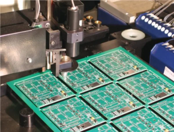
The Glass Transition Temperature (Tg) is the temperature threshold at which a PCB’s resin matrix changes from a hard, rigid state into a soft, flexible state.
Tg is not the melting point or maximum operating limit of the board. Instead, it marks the point where the substrate’s mechanical and physical properties degrade rapidly.
Beyond this temperature, the material expands much faster especially along the Z-axis putting intense mechanical strain on copper traces and Plated Through Holes (PTH).
For modern high reliability applications, working with an experienced PCB manufacturer like Victory PCB ensures that your design uses top tier substrate laminates compliant with ISO 9001 and IATF 16949 quality standards.
PCB laminates are grouped into primary Tg tiers depending on their resin formulations and thermal stability:
Standard Tg (130°C – 140°C): Traditional FR-4 suitable for basic consumer electronics operating in mild thermal environments.
Mid Tg (150°C – 160°C): Provides enhanced thermal stability for industrial controllers, power supplies, and outdoor LED drivers.
High Tg (≥ 170°C – 180°C): Essential for multi-layer boards, automotive electronics, and telecom servers. Learn more about High Tg PCB features and benefits for demanding thermal environments.
Ultra-High Tg (≥ 250°C): Used in military, aerospace, and down-hole drilling equipment where operating conditions exceed typical epoxy resin boundaries.
A fundamental rule in PCB design is keeping your device’s maximum continuous operating temperature well below the laminate’s Tg value.
A reliable benchmark is choosing a Tg material that is at least 20°C to 30°C higher than the highest expected temperature of your operating environment.
For example, if an industrial enclosure reaches internal temperatures of 130°C, you should select a material with a Tg of at least 150°C to 160°C to prevent resin softening and mechanical breakdown over time.
Modern environmental regulations mandate lead-free assembly, which requires significantly higher processing temperatures than traditional leaded soldering.
While traditional solder melts at around 183°C, lead-free solder profiles reach peak reflow temperatures between 245°C and 260°C.
Standard Tg boards exposed to these temperatures can suffer severe thermal shock and internal layer delamination, making High Tg materials (≥ 170°C) essential for multi-pass lead free assembly during rigid PCB fabrication.
Complex designs such as multilayer PCBs and HDI PCBs undergo multiple thermal cycles during fabrication and lamination.
As layer density increases, thermal expansion along the Z-axis poses a higher risk for via cracking and microvia failure. High Tg materials restrict this thermal expansion and safeguard internal connections.
Additionally, always account for localized thermal hotspots. High power components like MOSFETs, power management ICs, or drivers can create hot zones far hotter than the ambient enclosure temperature.
Your material selection should always be based on the peak temperature near these high power components.
To streamline your engineering verification and material specification, match your product requirements against the unified reference guide below:
| Target Application | Operating Temp Limit | Recommended Tg Grade | Key Companion Metrics | Suitable Material Grade |
| Consumer Electronics (Smartphones, Wearables, Smart Home) |
Less than 80°C | Standard Tg (130°C – 140°C) |
• Td: ≥ 300°C • Z-CTE: < 4.5% |
Standard FR-4 |
| Industrial & Outdoor (Motor Controls, Power Supplies, LED) |
80°C to 110°C | Mid Tg (150°C – 160°C) |
• Td: ≥ 325°C • Z-CTE: < 4.0% |
High CTI / Enhanced FR-4 |
| Automotive & Inverters (Under-hood, ECU, Power Inverters) |
110°C to 140°C | High Tg (≥ 170°C) |
• Td: ≥ 340°C • Z-CTE: < 3.5% |
Isola S1000-2, IT-1803 |
| Telecom & Servers (5G Base Stations, Data Centers, High-Layer HDI) |
110°C to 140°C (24/7 Heavy Load) |
High Tg (≥ 170°C) |
• Td: ≥ 350°C • T288: ≥ 15 min |
High Tg FR-4, Rogers Hybrid |
| Aerospace & Defense (Flight Controls, Avionics, Downhole) |
Greater than 150°C | Ultra-High Tg (≥ 250°C) |
• Td: ≥ 380°C • T288: ≥ 30 min |
Polyimide (PI) / Rigid-Flex |
Selecting the right Tg involves balancing long-term product reliability with bill of materials constraints.
High Tg laminates typically cost 15% to 30% more than standard FR-4 due to specialized resin formulations and additives. Furthermore, High Tg materials are harder and require adjusted drilling parameters during fabrication.
Leading manufacturers like Victory PCB maintain a robust raw material stock including standard FR-4, Mid/High Tg FR-4, Aluminum, Polyimide, and Rogers enabling rapid PCB prototyping and volume production without long material lead times.
Tg (Glass Transition Temperature) is the point where the resin softens and turns flexible, while Td (Decomposition Temperature) is the point where the laminate chemically breaks down and loses weight. Td is an irreversible chemical reaction, making high Td values critical for withstand lead-free reflow heat.
No, Tg indicates thermal stability, not thermal conductivity. If your board requires efficient heat dissipation, you should consider specialized aluminum PCB substrates or heavy copper designs rather than simply increasing the Tg rating.
While not strictly mandatory for simple 2 layer boards, High Tg or Mid Tg materials are strongly recommended for lead free assembly. Lead free reflow temperatures reach 240°C–260°C, which can cause severe thermal stress, warping, or delamination in standard FR-4 materials.
Selecting the ideal PCB Tg requires evaluating your continuous operating temperatures, assembly reflow demands, layer density, and overall budget. By building in a sufficient temperature buffer and pairing Tg with other thermal parameters like Td and CTE, you can guarantee high performance and durability across the entire lifecycle of your electronic product.
If you have questions about choosing the right material stackup or need expert guidance on your next circuit board design, please feel free to contact Victory PCB today. Our experienced engineering team is ready to review your Gerber files and help you build reliable, cost effective PCBs tailored to your exact application requirements.